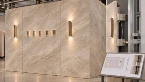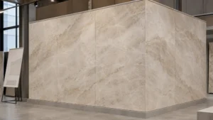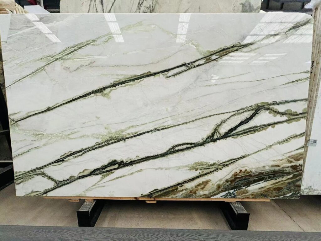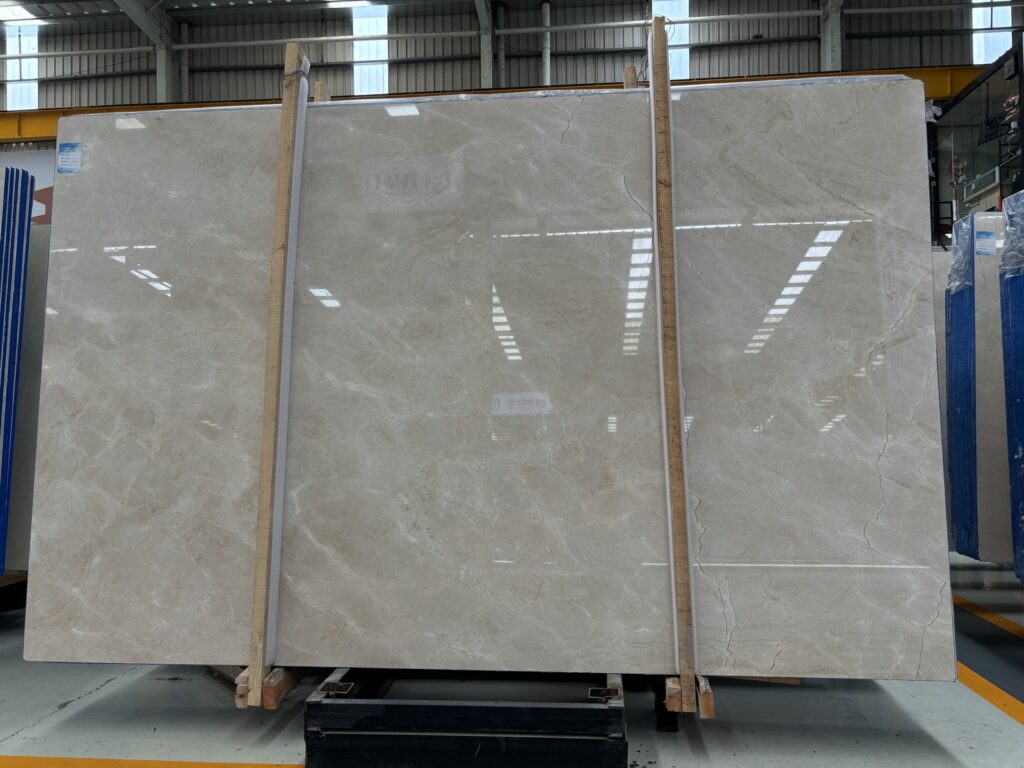

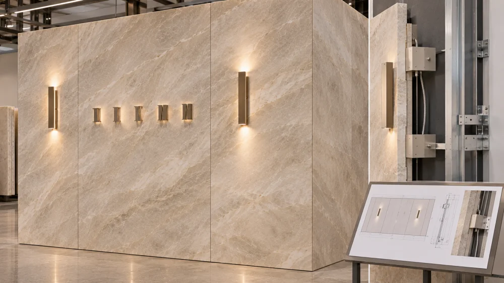
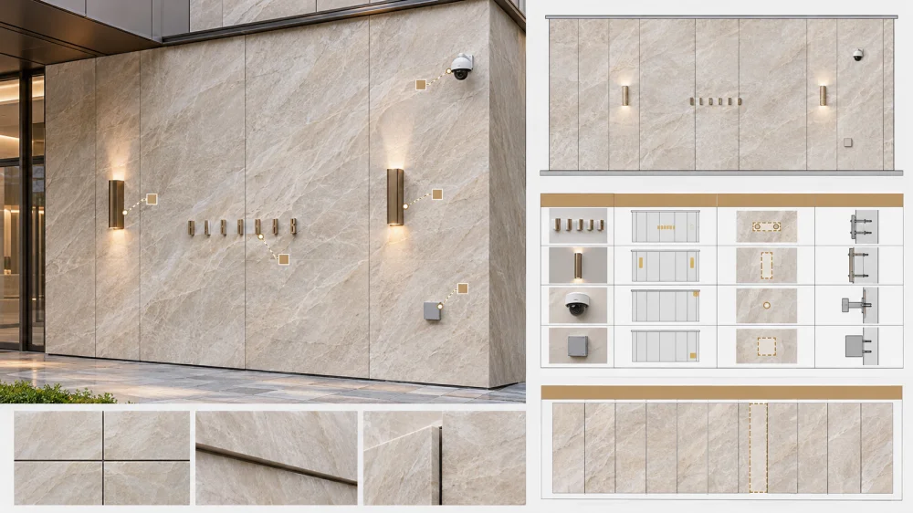
Quartzite facade penetrations should be coordinated before the stone panels are cut whenever signs, lights, cameras, brackets, conduits or other attachments must pass through or attach near the finished stone face. Record the exact panel ID, attachment purpose, opening or drilling location, required backing or structure, stone-face relationship and responsible trade. Do not let the stone panel become the assumed structural support for an attachment unless the project-specific design explicitly makes it part of the engineered load path.
Penetration Control ChainAttachment → Required Location → Stone Panel → Penetration / Clearance → Backing or Structure → Fabrication → Site Installation → As-Built Record
The objective is to make every intentional hole or interface traceable before somebody arrives on site with a drill and tries to reconstruct the design from an elevation rendering.
A Quartzite facade penetration is a controlled opening, drilled hole, slot, clearance zone or other interface created in or through a Quartzite panel so another building component can pass through, attach, connect or be serviced.
Examples can include:
The stone fabricator should not receive:
“Please drill holes for the sign.”
without enough information to identify what those holes belong to.
Build an attachment schedule first.
For each item, identify:
This creates one coordinated source instead of separate signage, lighting and stone drawings carrying different locations.
Coordination RuleA stone hole is not an isolated stone detail.
It is the visible end of another trade’s requirement, and that requirement should remain identifiable from design through fabrication and installation.
This question should be resolved before drilling.
A sign, luminaire, bracket or another attachment may create:
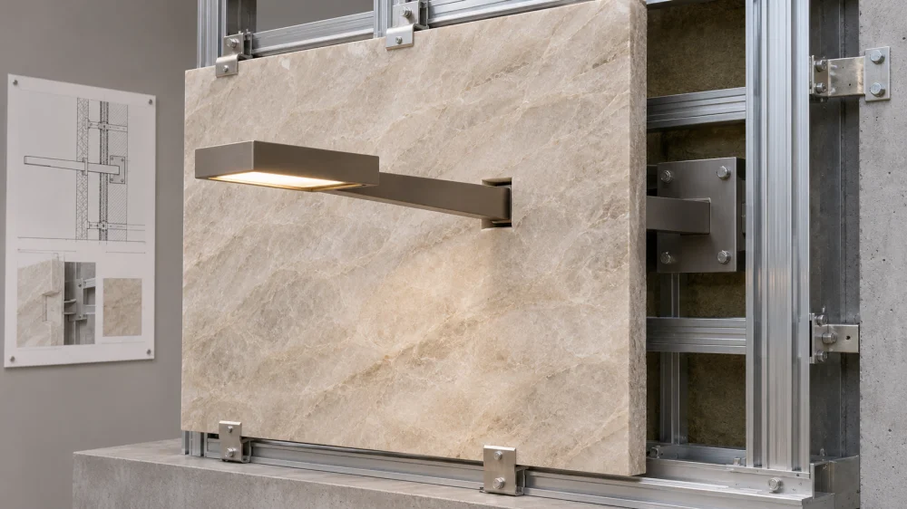
The Natural Stone Institute’s current vertical-surface guidance covers multiple mechanically anchored, adhesively attached and panelized stone installation systems and specifically treats anchorage as part of the vertical-stone assembly. It does not establish one universal fixing method for signs or lights. :chatgpt-content-reference{index=”1″}
That leads to an important project boundary:
The Quartzite panel should not automatically be treated as the structural support for an unrelated attachment.
Depending on the design, the attachment may need to connect through the stone to:
The responsible designer, attachment supplier and facade / structural team should define that load path for the actual project.
Do not locate a hole only from a cropped panel photograph.
Use the current fabrication geometry.
A controlled location may reference:
The stone drawing should clearly distinguish:
visual markup
from
fabrication geometry.
The site’s annotated-photo fabrication guide makes the same distinction: photos can communicate design intent, but final openings, hole locations and dimensions should remain tied to the current drawing, verified CAD, template or other approved fabrication basis. :chatgpt-content-reference{index=”2″}
The design should consider the actual surrounding stone geometry.
Potential review points include:
This article should not invent one universal minimum edge distance.
The acceptable geometry depends on:
If a planned opening falls near a fissure-like condition, repair or strongly changing mineral zone, first map the condition to the actual panel.
Then ask:
Does this location remain appropriate for the finished attachment geometry?
Do not diagnose the visible feature from a photograph and invent a universal offset.
A useful facade penetration register can separate them.
| Attachment Type | Typical Stone Coordination | Other Interface |
| Individual Sign Letters | Multiple controlled stud / cable locations | Signage template and backing |
| Wall Light | Mounting and cable / conduit opening | Electrical box / bracket / structure |
| Camera / Sensor | Small attachment footprint and cable route | Data / power / service access |
| Large Projecting Sign | Clearance through stone and coordinated panel geometry | Engineered structural support |
| Linear Lighting | Repeated slot / hole / bracket relationship | Driver, wiring and maintenance strategy |
This keeps “facade penetrations” from becoming one vague category.
Where they materially affect the visible stone composition, yes.
Imagine a large Patagonia Quartzite feature wall.
The designer wants individual metal sign letters centered across the elevation.
If the letters are coordinated only after the slab layout is approved, the studs may land:
The better sequence is:
Architectural Elevation → Sign / Light Geometry → Stone Panelization → Slab Allocation → Penetration Map → Fabrication Release
The visual position and technical fixing position should be coordinated rather than designed in separate document streams.
There is no universal answer.
Factory cutting can be useful when:

Site drilling may still be appropriate for project-specific conditions where final verified site information is needed.
But:
site drilling should not mean uncontrolled drilling.
Before work begins, the project should identify:
Late-Drilling WarningThe most dangerous information gap is not “factory drilling” versus “site drilling.”
It is a hole being added after the responsible teams have stopped checking which stone panel, backing condition, anchor zone and drawing revision it belongs to.
Some penetrations are only the clearance through the stone.
The final assembly may also contain:
Those items can change the required opening geometry.
For example, the visible light fitting may be 100 mm wide, but its concealed mounting plate or electrical box can require a different stone clearance.
Do not fabricate the stone opening from the visible fixture size alone.
An exterior Quartzite facade penetration can pass through more than the stone face.
It may interact with:
The 2024 Dimension Stone Design Manual includes revised vertical-installation guidance and expanded anchorage graphics, including modern facade-system and thermal-interface considerations. :chatgpt-content-reference{index=”3″}
The stone fabricator can coordinate the physical Quartzite opening.
The complete exterior penetration—including water, air, thermal, structural and code performance—should remain with the appropriate facade and project design team.
Every penetration that affects fabrication should be linked to a stable finished-piece identity.
For example:
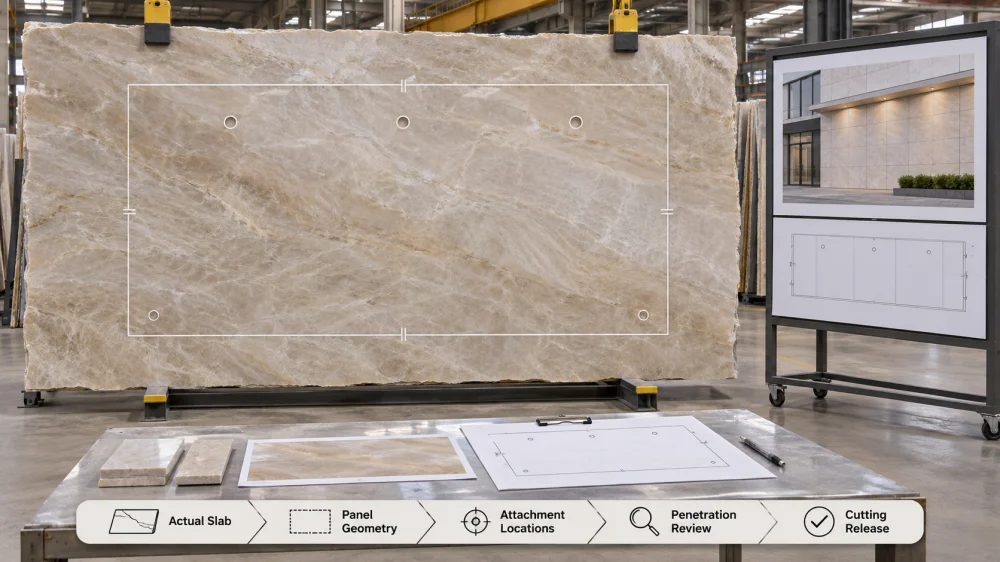
Panel W-18
Taj Mahal Quartzite
Main Entrance Elevation
Sign Attachment S-04 / S-05
Lighting Penetration L-02
Current Drawing Revision R06
Then connect W-18 back to the source slab.
A useful chain becomes:
Board → Panel W-18 → Attachment IDs → Hole Geometry → Factory QC → Crate → Installed Location
The Quartzite layout approval guide similarly emphasizes that approval belongs to an exact slab set and current revision, and that changes affecting visible layout or openings should not silently inherit an earlier approval. :chatgpt-content-reference{index=”4″}
Do not check only whether “a hole exists.”
Review the penetration within the complete finished panel.
| QC Check | Evidence |
| Correct Panel | Stable piece ID and visible face |
| Correct Revision | Current drawing / template reference |
| Penetration Location | Controlled measurement against approved datum |
| Opening Geometry | Hole / slot / clearance matches current fabrication basis |
| Stone Around Opening | Visible edge condition and surrounding stone reviewed |
| Attachment Relationship | Template or representative interface where required |
| Final Panel Condition | Complete finished-piece photograph before packing |
Do not invent readable tolerance values in photographs unless they are genuinely part of the project’s approved QC specification.
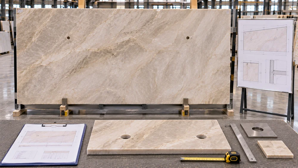
Treat the change as a controlled interface revision.
Do not simply send the factory a screenshot showing:
“Move these two holes.”
Check whether the revision changes:
If the production drawing changes, the current revision should replace the superseded fabrication basis rather than leaving the revision only in chat messages.
The site installer should be able to answer:
Which attachment belongs to which stone panel?
without reconstructing the project from multiple unrelated drawings.
A useful site package can contain:
The Quartzite Factory-to-Site Handover Document Index uses this same traceability principle: piece IDs should connect drawings, QC, packing and installation rather than change names between project stages. :chatgpt-content-reference{index=”5″}
The penetration register should become an as-built record where the project requires future maintenance or replacement.
Record:
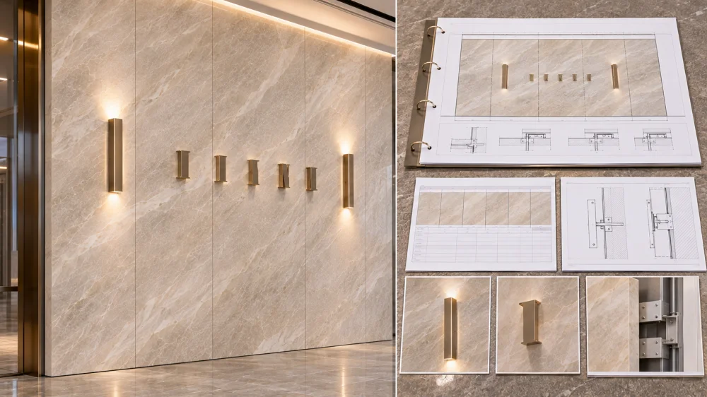
Attachment ID
Installed Panel ID
Final Location
Attachment Type
Stone Penetration Type
Back Support / Interface Reference
Final Drawing Revision
Installed Photograph
Access / Maintenance Note
Date / Status
This becomes useful when:
As-Built RuleA completed facade should not leave the future maintenance team guessing which holes were intentional, what they support or what lies behind the stone.
Penetration coordination becomes much clearer when responsibility is explicit.
| Decision | Typical Responsible Input |
| Attachment Position | Architect / signage / lighting / relevant designer |
| Attachment Load / Support | Responsible structural / facade / attachment-system designer |
| Stone Panel Geometry | Stone fabricator using current approved information |
| Electrical / Data Interface | Relevant MEP / specialist contractor |
| Factory Penetration QC | Stone fabricator / supplier under agreed QC scope |
| Site Attachment | Responsible installer under current project documents |
The exact responsibility structure depends on the contract.
The important point is that the stone supplier should not silently inherit responsibility for the engineering of every item attached to the facade merely because the opening passes through the stone.
Yes, but the stone opening and the attachment support should be coordinated as one project interface. The responsible design team should define where the attachment load goes, while the stone fabricator coordinates the required panel opening or clearance with the current fabrication geometry.
Do not assume that automatically. Depending on the attachment, the load may need to transfer through the stone to structural backing, a subframe, dedicated bracket or another engineered support. The actual load path should be established for the project.
Either can be appropriate depending on how final the attachment geometry and site information are. Factory drilling offers controlled fabrication and QC when locations are confirmed; site drilling may be needed where final verified conditions control. In both cases, the panel ID, approved location, backing condition and responsible party should be known before drilling.
This article does not apply one universal value. Appropriate geometry depends on the actual stone, panel thickness, penetration size and shape, attachment load, support system, fabrication method and project-specific engineering or fabrication requirements.
Identify the condition and its exact panel location first. Then review whether the planned penetration remains suitable in that finished geometry. Do not classify the stone only from a close-up or apply an invented universal offset.
Issue a controlled revision. Check whether the new position changes the panel geometry, remaining stone, backing, fixture footprint or another approved interface before adding or moving holes. Do not rely only on an informal marked-up photograph.
Keep the attachment ID, stone panel ID, final location, penetration type, relevant backing or support reference, final drawing revision and installed photographs where future maintenance or replacement may require them.
Send the current facade elevation, stone panel IDs and dimensions, selected Quartzite or board references, attachment schedule, sign or light templates, current hole or opening geometry, backing or structural information from the responsible designer, relevant electrical or service interfaces, finish, destination and whether each penetration is intended for factory or site fabrication.
Penetration Release GateDo not release a hole because its position looks correct on the elevation.
Release it when the project can identify the correct stone panel, current dimensional location, attachment purpose, backing / support relationship, responsible trade and current drawing revision.
Buyer Next Step: Before stone fabrication, request one coordinated penetration schedule that connects every sign, light and other attachment to the exact Quartzite panel it affects.