Mitras de Cascata em Quartizito: Por que a Sequência de Corte é Importante
Post navigation
Resumo Rápido
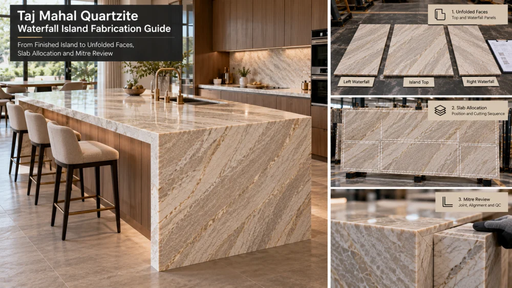
A Quartzite waterfall mitre should be planned as a relationship between visible stone faces, not simply specified as a mitred edge. Before cutting, identify the island top, waterfall return, viewing priority, piece orientation, actual slab positions, mitre edges and current drawing revision. Then review how saw kerf, trimming and edge preparation affect the stone between the two visible faces. The goal is controlled visual continuity from the actual Natural Quartzite slab—not a promise that every vein will meet perfectly around the finished corner.
Imagine a Natural Quartzite slab with one broad mineral movement running diagonally across it.
The designer wants that movement to travel across the kitchen island and then appear to continue down the waterfall end.
On a rendering, the solution looks simple:
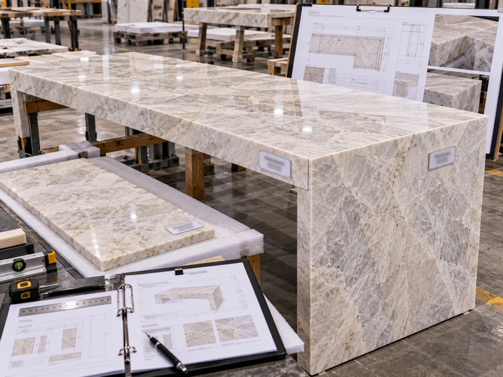
mont-blanc-quartzite-waterfall-developed-corner
Top → 90° Corner → Waterfall Panel.
But the stone is not folded like paper.
Two separate finished faces must first be positioned and cut from a physical slab. Material exists between those faces, and some of it is consumed during cutting, trimming and mitre preparation.
That is why the cutting sequence matters.
Start with the Finished Corner—Then Unfold It
FINISHED VIEW
Horizontal island top meets a vertical Natural Quartzite waterfall return at the visible outside corner.
↓
UNFOLD THE CORNER
Show the top and waterfall panel as separate flat visible faces so their intended pattern relationship can be reviewed.
↓
PLACE BOTH PIECES ON THE ACTUAL SLAB
Only now can the project see where each piece begins, where the mitre edges occur and what stone lies between them.
This developed or unfolded view is one of the most useful ways to review a Quartzite waterfall mitre.
It turns a three-dimensional design intention into something that can be compared directly with the actual slab.
Step 1 — Identify Every Visible Face
Before discussing vein matching, establish what people will actually see.
A1 — ISLAND TOP
Main horizontal surface and usually the largest visual field.
A2 — WATERFALL FACE
Vertical face seen from the end or approach to the island.
M1 — MITRE LINE
The visual hinge where the two fabricated components meet.
A3 — RETURN / INSIDE FACE
Relevant where another face remains visible after installation.
Do not rely only on instructions such as “match the vein” ou “continue the pattern.”
Those phrases do not identify which faces matter most or what relationship the project expects.
Step 2 — Decide Which View Has Priority
A waterfall island can be seen from several directions.
The most important view may be:
the entrance into the kitchen;
the long side of the island;
the waterfall end;
the seating side;
the living area looking toward the kitchen; or
two waterfall ends viewed together.
The layout does not always need to give every face equal visual priority.
Prioridade de Design
Tell the fabricator which view is most important before the slab is allocated. A dramatic mineral feature that works beautifully on the top may become too dominant when turned vertically onto the waterfall face.
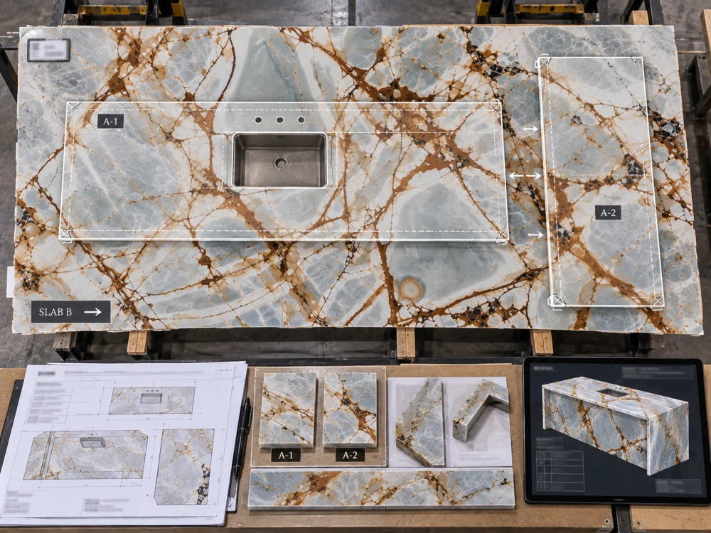
Step 3 — Put the Top and Waterfall on the Actual Slab
Once the visible faces and viewing priority are understood, position the pieces on the selected Natural Quartzite slab.
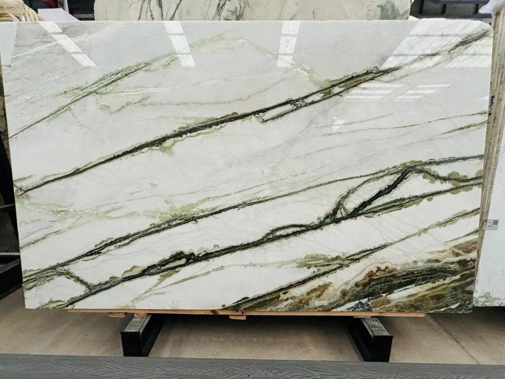
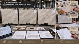
blue-roma-quartzite-waterfall-slab-cutting-layout
A useful layout should make it possible to identify:
Actual Slab → A1 Top Position → A2 Waterfall Position → M1 Mitre Relationship
For visually directional Quartzite, add orientation marks to the important pieces.
However, an arrow should communicate a defined project meaning rather than stand alone. The related guide to Quartzite vein-direction symbols for shop drawings explains why direction marks should be coordinated with visible faces, piece IDs, seams and the actual slab layout.
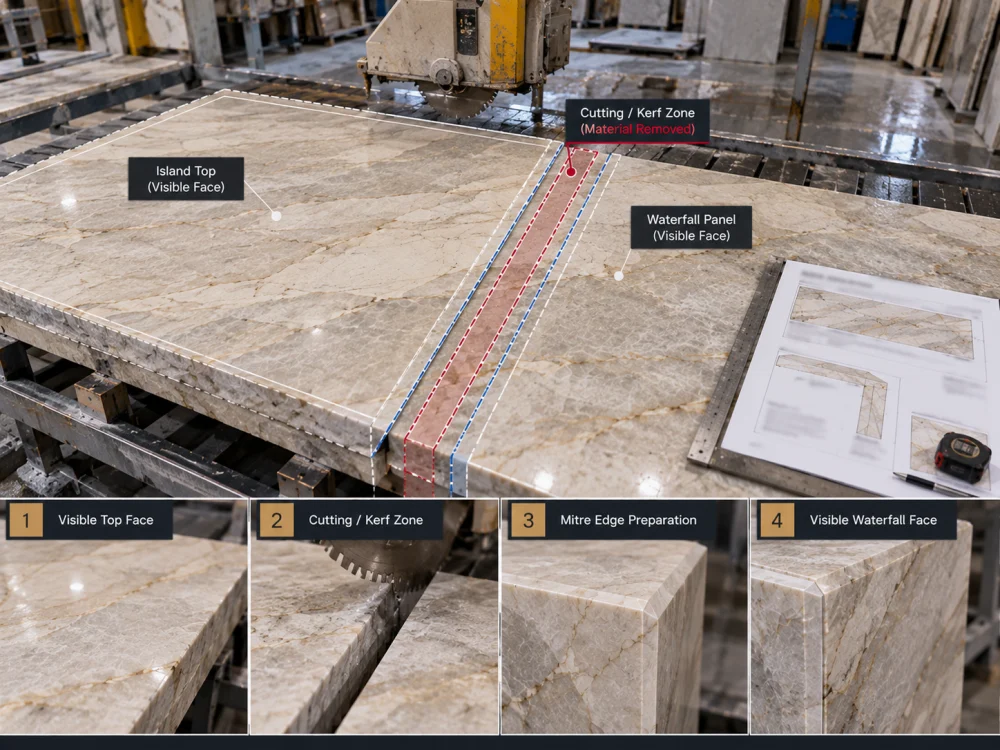
Now Add the Material That Will Disappear
This is the point that a conceptual rendering usually does not show.
THE DIGITAL LAYOUT IS NOT THE FINAL CUT EDGE
Visible Top Face
↓
Cut / Kerf / Trim / Edge-Preparation Zone
↓
Visible Waterfall Face
Saw kerf removes material.
Trimming removes material.
Mitre preparation changes the relationship between the untouched slab and the finished edge.
Final fitting and refinement may also influence what appears at the corner.
Therefore, two mineral lines that appear to touch perfectly on an idealized screen layout should not automatically be expected to meet with zero visual displacement after fabrication.
Why Cutting Sequence Matters
The cutting sequence explains how the approved slab area becomes actual fabricated pieces.
Consider a simplified example.
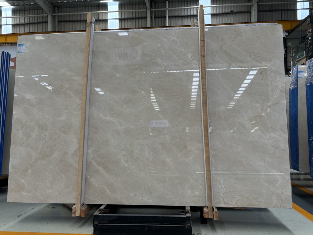
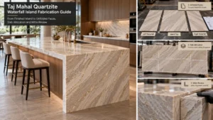
taj-mahal-quartzite-waterfall-mitre-kerf-trim
01 — Establish the Approved Slab Layout
Confirm the current A1 and A2 positions against the actual slab.
02 — Identify the Relevant Cut Boundaries
Understand which slab areas become finished faces and which areas become trim or waste.
03 — Separate the Components
The fabricator converts the planned slab allocation into the required top and return pieces using the approved process.
04 — Prepare the Mitre Edges
The project-specific edge geometry is fabricated on the related edges.
05 — Trial the Relationship
Check how the two visible faces read together after real fabrication has replaced the conceptual digital relationship.
This does not prescribe a universal factory machining sequence.
The responsible fabricator determines the actual cutting, edge preparation, reinforcement, handling and assembly process for the project.
For the buyer, the purpose of the sequence is to understand where the approved visual relationship can change before the finished corner exists.
The Pattern Does Not Literally “Bend” Around the Corner
This distinction is important when discussing waterfall vein matching.
The stone pattern exists on two fabricated surfaces that meet at a joint.
The goal can be strong visual continuity, but that does not mean every individual mineral line can or should meet perfectly.
Expectation
Better Project Interpretation
Every vein must meet exactly
Review the realistic visual relationship produced from the actual slab and fabrication allowances.
The pattern should look continuous
Define what continuity means for this slab: movement, tone, scale, feature relationship or another stated visual priority.
The CAD layout matches, so fabrication will match exactly
Use CAD to communicate intent, then account for real cutting and edge preparation.
Compare the Corner in Its Developed State
Before the pieces are fabricated, temporarily ignore the finished 90-degree form.
Look at the two visible faces flat.
A1 — ISLAND TOP
Which stone movement approaches the proposed mitre edge?
M1 — TRANSITION
What material lies between the two intended visible faces, and what part may be consumed during fabrication?
A2 — WATERFALL
Which stone movement begins immediately after the finished corner?
This developed-corner review is particularly useful for active materials such as Blue Roma Quartzite, Patagonia Quartzite and other stones with strong localized geological features.
Two Layouts Can Use the Same Slab Very Differently
Suppose one slab contains a dramatic crystalline area close to the proposed waterfall transition.
OPTION A — FEATURE THE CORNER
Position the active geological area close to the mitre so the transition becomes a strong visual feature.
OPTION B — QUIET THE CORNER
Move the active feature farther into the island top or waterfall face and use a calmer slab area at the transition.
Neither option is automatically correct.
The appropriate choice depends on the actual slab, design intent, room view, usable stone and fabricator review.
Sink and Cooktop Openings Can Change the Waterfall Layout
The waterfall cannot be planned independently from the rest of the island.
A visually ideal A1 top position may place a sink or cooktop opening in an undesirable location.
Moving the top to solve the opening may then change the stone arriving at M1.
Changing M1 changes the beginning of A2.
One Change Can Travel Through the Entire Composition
Sink / Cooktop Position
↓
Island Top Position
↓
Mitre Edge Position
↓
Waterfall Starting Area
↓
Finished Visual Relationship
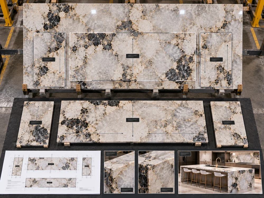
Two Waterfall Ends Need to Be Reviewed Together
A double-waterfall island adds another decision.
Now the composition contains:
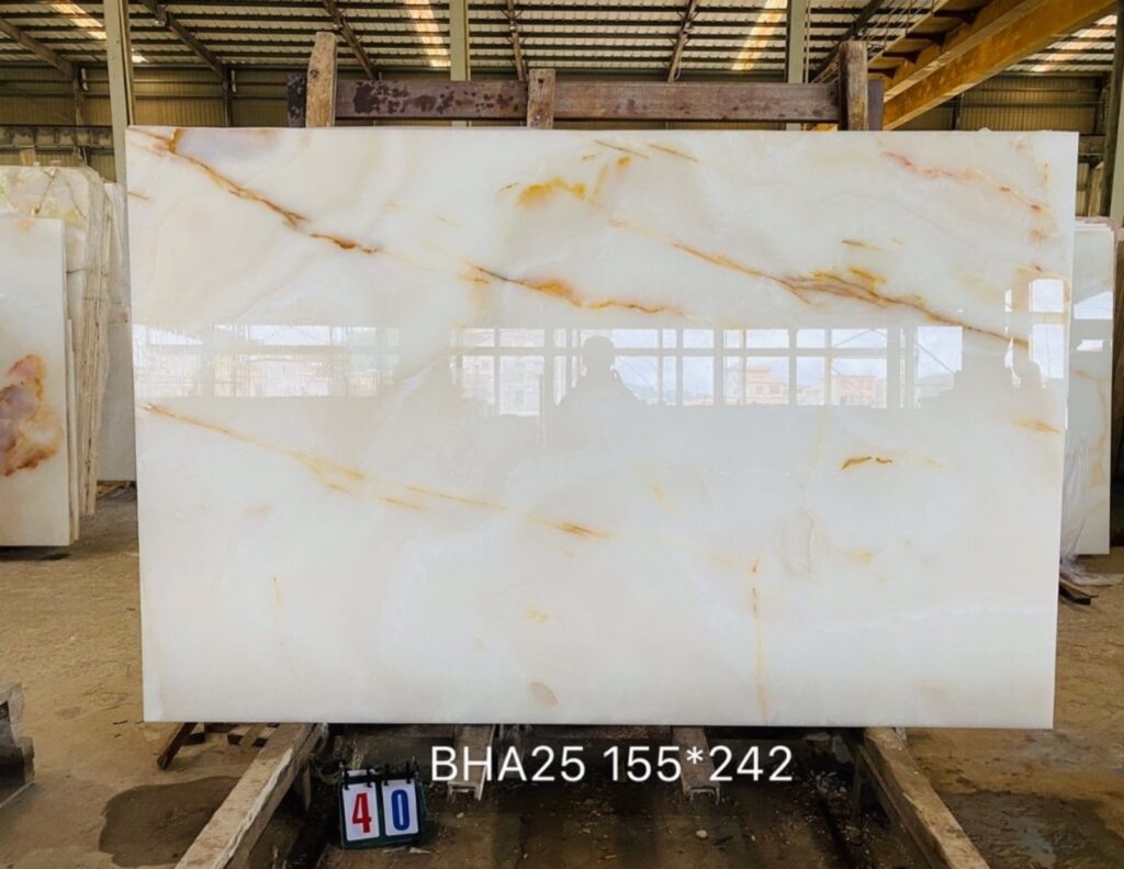
patagonia-quartzite-double-waterfall-layout
A2 Left Waterfall ← A1 Island Top → A3 Right Waterfall
Do not assume that simply mirroring the two side-panel shapes creates the desired visual relationship.
The actual slab allocation may produce:
two visually related ends;
one stronger and one quieter end;
deliberately different geological features; or
a need to use more than one slab.
Review both ends on the same coordinated layout before deciding what “matching” means for the project.
What Happens If the Island Dimension Changes?
A small dimensional revision can have a larger visual consequence than expected.
For example, increasing the island length may move:
Cut Line → Mitre Position → Mineral Feature → Waterfall Start
Therefore, if island length, width, overhang, return depth, sink position or another relevant dimension changes after layout approval, do not assume the original waterfall approval remains valid.
Revision Rule
Dimension change → identify affected pieces → compare against the approved slab layout → revise the layout where necessary → obtain the required approval before cutting.
Keep Orientation with the Piece ID
A directional arrow is more useful when attached to a specific component.
Por exemplo:
A1 → Island top visual direction
A2 ↓ Left waterfall orientation
A3 ↓ Right waterfall orientation
The same piece IDs should remain recognizable across the relevant shop drawing, slab layout, fabrication record and QC documentation where practical.
This reduces the risk of a panel being rotated or interpreted differently after the original layout discussion.
From Flat Slab to Finished Corner
01 — SELECTED NATURAL QUARTZITE SLAB
02 — FINISHED PIECE OUTLINES
A1 top + A2 waterfall + other required components
03 — VISIBLE FACES + ORIENTATION
Define what the viewer is intended to see.
04 — MITRE RELATIONSHIP
Review the stone immediately approaching both sides of M1.
05 — CUTTING / TRIM ALLOWANCE REVIEW
Understand that material between conceptual faces may be consumed.
06 — CURRENT DRAWING + LAYOUT APPROVAL
07 — FABRICATION
Actual machining follows the responsible fabricator’s approved process.
The buyer does not need to approve proprietary saw programming or factory machining instructions.
The useful buyer-side approval is the visual and project relationship.
Buyer / Designer Review
Fabricator Review
Selected slab and intended visible areas
Actual material suitability for the proposed fabrication
Primary viewing direction
Cutting and machining process
Top / waterfall visual relationship
Kerf, trimming and fabrication allowances
Piece orientation and visible-face intent
Project-specific mitre preparation, reinforcement and handling
Current approved layout revision
Fabrication release within the responsible technical scope
Before the Quartzite Waterfall Is Released for Cutting
□ Exact slab or board reference identified
cristallo-quartzite-waterfall-mitre-trial-fit-qc
□ Current island dimensions confirmed
□ Island top piece identified
□ Waterfall panel or panels identified
□ Visible faces marked
□ Primary viewing direction understood
□ Orientation marks defined
□ Sink / cooktop openings coordinated where applicable
□ Mitre relationship shown on the actual slab layout
□ Natural features near critical cut areas reviewed where relevant
□ Current drawing revision identified
□ Buyer / designer visual approval recorded
□ Responsible fabricator has completed the applicable technical review before cutting
Perguntas frequentes
1. What is a Quartzite waterfall mitre?
A Quartzite waterfall mitre is a fabricated corner where a horizontal Natural Quartzite countertop meets a vertical waterfall panel through related mitred edges. The design can create a visually continuous transition, but the final appearance depends on the actual slab layout and fabrication process.
2. Why does the cutting sequence matter for a Quartzite waterfall mitre?
The cutting sequence helps explain how the approved slab area becomes separate fabricated pieces. Saw kerf, trimming and mitre preparation can consume material between the intended visible faces, so the final corner relationship should not be judged only from an idealized digital layout.
3. Can Quartzite veins match perfectly around a waterfall corner?
Perfect line-for-line matching should not be assumed. Natural Quartzite varies, and fabrication removes or modifies material at the transition. A more useful goal is an approved visual relationship based on the actual slab, piece positions, mitre location and fabrication allowances.
4. What should be shown on a Quartzite waterfall layout?
Show the selected slab, top and waterfall piece positions, piece IDs, visible faces, orientation, important dimensions, openings, mitre relationship and current drawing revision. The responsible fabricator should add the project-specific technical information needed for fabrication review.
5. Should the island top and waterfall panel be planned together?
Yes, when their visual relationship matters. Planning them independently can lose the opportunity to coordinate movement, tone and important geological features around the finished corner.
6. What happens if the island dimensions change after the waterfall layout is approved?
Review the affected layout again before cutting. A dimensional change can move the top piece, mitre line or waterfall starting area into a different part of the slab, changing the previously approved visual relationship.
7. Do two waterfall ends need separate piece IDs?
Using separate piece IDs is useful because each waterfall panel has its own slab position, orientation and visible relationship to the island top. Both ends can then be reviewed together without treating them as automatically identical.
8. What should I send HRST STONE for a Quartzite waterfall island?
Send Josh the Natural Quartzite material and slab references, current island dimensions, plan and elevations, sink or cooktop information where applicable, waterfall dimensions, visible-face priorities, preferred stone movement, finish, current drawing revision and delivery destination.
Waterfall Layout Review with HRST STONE
HRST STONE can coordinate actual Natural Quartzite slab photographs, CAD/shop drawings, piece IDs, visible-face orientation, cutting layouts, fabrication records, trial review, QC photographs and reinforced export packing around the confirmed project scope. For visually important waterfall islands, send Josh the current drawings and slab references before fabrication so the top and vertical returns can be reviewed as one composition.
Hi, I am the author of this article. I have been working in the field of Natural Stone for more than 15 years. If you need customized Natural Stone services, please feel free to contact me.
Fabricante e Fornecedor de Mármore, Granito, Quartzito, Ágata da China - HRST STONE
Bem-vindo à HRST STONE!
Olá, gostaria de saber mais sobre seus produtos. Você poderia compartilhar informações sobre preços, quantidade mínima de pedido, opções de personalização e amostras?