Quarzit-Schneidepläne: Anzeige der Plattennummern auf jedem fertigen Stück
Post navigation
Kurze Zusammenfassung
A quartzite cutting plan should show more than where pieces fit on a slab. For projects where appearance, sequence, or traceability matters, each finished piece should carry a unique piece ID and remain linked to the number of the source slab from which it will be cut. That relationship should continue through layout approval, fabrication, QC, packing, and installation documentation.
A quartzite cutting plan connects an approved Natural Quartzite slab with the finished components required by a project. For a simple job, the layout may mainly control material yield. For a vein-sensitive kitchen island, feature wall, reception counter, fireplace, or multi-room project, the same drawing also becomes an important visual and production-control document.
The key principle is straightforward: the project team should be able to identify which finished piece comes from which approved slab.
This is why slab numbers and finished-piece IDs should not disappear once cutting begins.
The Two Numbers a Quartzite Cutting Plan Needs
SLAB NUMBER
Identifies the physical Natural Quartzite slab used as the source material.
PIECE ID
Identifies the finished countertop, panel, return, backsplash, waterfall end, or other fabricated component.
These references perform different jobs. The slab number answers “Where did this stone come from?” The piece ID answers “Where does this component belong?”
A controlled cutting plan connects the two.
Example: Linking Slabs to Finished Pieces
Consider a quartzite kitchen requiring two approved slabs. The cutting plan might use a structure like this:
Plattennummer
Piece ID
Finished Component
Key Control
SLAB-01
K-01
Island Top A
Principal visible area
SLAB-01
K-02
Waterfall End A
Pattern relationship to K-01
SLAB-02
K-03
Island Top B
Relationship to K-01
SLAB-02
K-04
Waterfall End B
Pattern relationship to K-03
The actual naming system can vary. What matters is that the references are unique, consistent, and used throughout the project documentation.
What Should Be Shown on the Slab Layout?
A useful quartzite cutting plan places the proposed finished components over the actual slab or a reliable scaled representation of it.
Depending on the project, the layout may need to show:
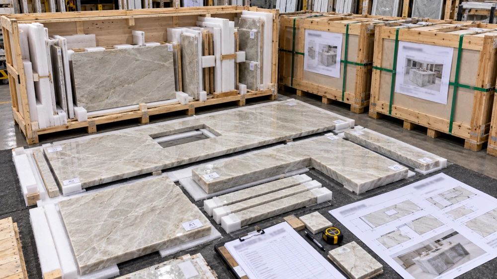
taj-mahal-quartzite-slab-cutting-layout
slab number;
slab dimensions and usable boundaries;
finished-piece outlines;
unique piece IDs;
finished dimensions;
orientation or directional requirements;
cutouts and openings;
visible edges and returns;
seam relationships;
mitered or waterfall relationships; and
areas requiring buyer review before cutting.
Not every project needs the same amount of information. The drawing should contain enough information to control the actual fabrication and visual intent without becoming unnecessarily complicated.
Why the Actual Slab Image Matters
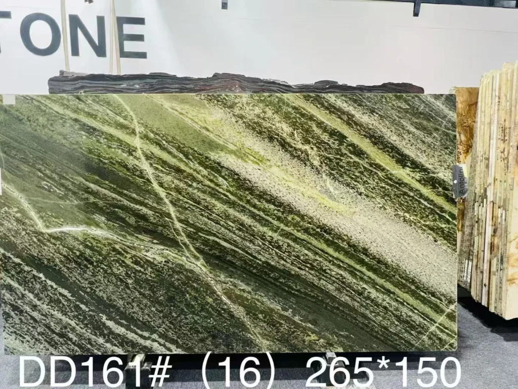
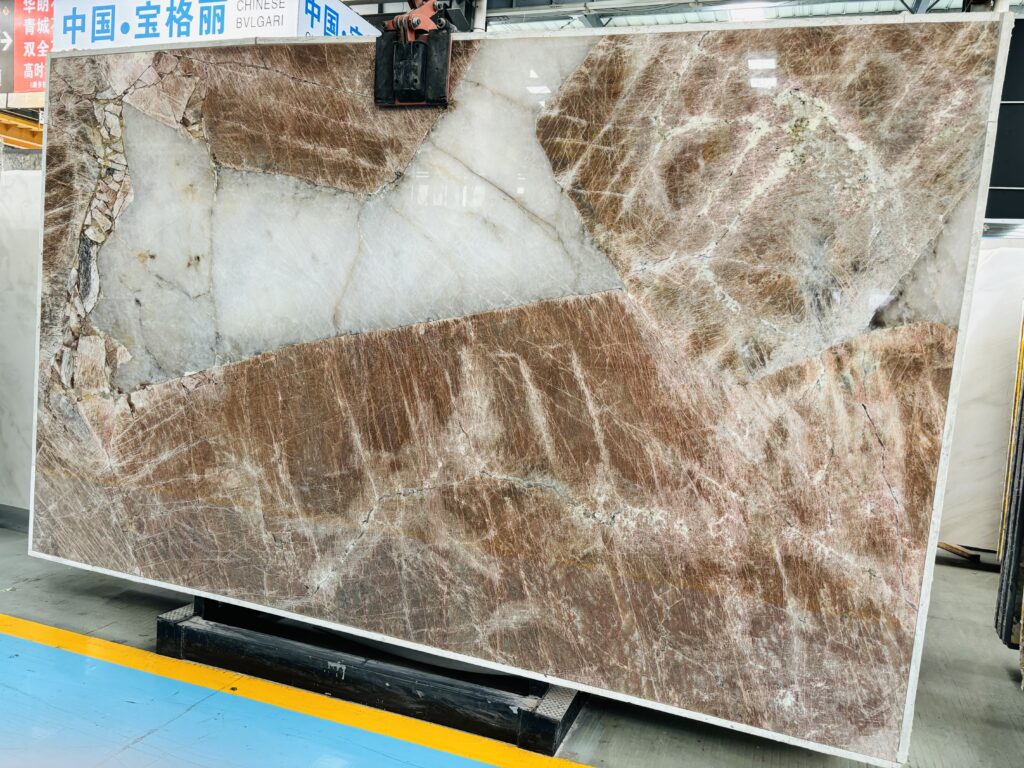
For Natural Quartzite with strong movement, crystalline zones, contrasting mineral structures, or directional veining, a generic rectangular slab outline cannot communicate the complete design decision.
Where practical, the cutting proposal should be reviewed against the actual selected slab image or another controlled slab reference.
LAYOUT PRINCIPLE
The buyer should be able to see not only whether a piece fits on the slab, but also which part of the natural pattern will appear on that finished piece.
This is especially useful for statement islands, waterfall ends, large wall panels, fireplace surrounds, furniture tops, and other applications where pattern placement affects the final design.
Slab Number → Piece ID → Installation Location
A strong numbering system creates a simple traceability chain.
This relationship is much more useful than using one number for everything. It allows production teams to identify the source stone while installers can identify the destination of the finished component.
Keep Related Pieces Visually Connected
Piece numbering should support the design logic rather than only inventory control.
If two pieces form a visual relationship—such as a countertop and waterfall end, two sides of a mitered corner, sequential wall panels, or neighboring countertop sections—the cutting plan should make that relationship obvious.
Zum Beispiel:
Relationship
Drawing Control
Island + Waterfall
Show which edge transitions into the vertical component.
Adjacent Wall Panels
Maintain panel sequence and orientation.
Countertop Sections
Identify seam partners and visible direction.
Mitered Components
Link mating pieces and edge orientation.
Do Not Optimize Yield Before Visual Priorities Are Clear
Material yield matters because poor nesting can increase slab requirements and project cost. But maximum material utilization is not always the same as the best finished layout.
A cutting plan that tightly fills every available area may place a dominant natural feature through an unwanted location, reverse the intended movement between adjoining pieces, or separate two components that should visually relate to each other.
Buyer Decision
Decide which requirement has priority: maximum yield, principal-view appearance, vein continuity, specific feature placement, or a balance between them. The fabricator can then develop the cutting plan around an explicit objective rather than guessing.
Approve the Cutting Plan Before Production Release
mont-blanc-quartzite-cutting-plan-fabrication
A layout becomes most valuable when it forms part of the approval process rather than being prepared only for internal factory use.
Before cutting, the project team should confirm the current drawing revision, selected slab numbers, piece IDs, orientation, visible surfaces, key seams, cutouts, and important visual relationships.
If the buyer requests a layout change, issue or approve a revised cutting plan. Avoid allowing an outdated screenshot or earlier drawing revision to remain in circulation after the layout has changed.
What Happens When the Cutting Plan Changes?
Changes are common. Site dimensions may be updated, appliance information may change, a seam may move, or a replacement slab may be introduced.
When that happens, the affected references should be updated systematically.
01 — Identify the Change
Record the affected dimensions, pieces, slab, or layout relationship.
02 — Update the Layout
Revise piece positions and IDs where required.
03 — Recheck Yield & Visual Placement
Confirm that the revised arrangement remains feasible.
04 — Issue the New Revision
Make the current cutting plan identifiable.
05 — Release Only the Approved Revision
Production should work from the controlled current document.
Carry Piece IDs Into Fabrication QC
quartzite-finished-piece-qc-dry-lay-traceability
Once the slab is cut, the original layout is no longer physically visible as one complete slab. Piece identification becomes the bridge back to the approved plan.
During fabrication and final QC, the project record can use each piece ID to check the applicable dimensions, finish, edge work, cutouts, orientation, quantity, and visual relationship.
QC photographs are also more useful when the piece reference is clear. Instead of receiving dozens of unrelated factory images, an overseas buyer can compare the inspection evidence with the approved cutting plan.
Piece Numbering Should Continue Into Packing
The numbering system should not end when fabrication passes QC.
For export orders, the packing documentation should allow the receiving team to identify components without repeatedly unpacking or handling stone unnecessarily.
Document / Item
Reference to Maintain
Approved Cutting Plan
Slab numbers + piece IDs
Finished Components
Teilstück-IDs
QC Record
Piece IDs / drawing revision
Packing List
Piece IDs + crate allocation
Installation Reference
Piece IDs + final location
quartzite-piece-number-packing-traceability
Why This Matters More for International Quartzite Orders
For local fabrication, a designer or installer may be able to visit the workshop and physically review the pieces. International procurement often relies much more heavily on drawings, photographs, videos, QC files, packing lists, and remote approvals.
A traceable quartzite cutting plan gives each team the same reference language.
The designer can review visual placement. The fabricator can follow the approved nesting. QC can inspect identifiable components. The packing team can allocate the correct pieces to crates. The receiving team can confirm quantities, and the installer can determine where each component belongs.
The numbering system therefore becomes a practical communication tool across the entire supply chain.
Cutting Plan Checklist Before Release
□ Correct slab numbers shown
□ Actual selected slab references used where required
□ Every finished component has a unique piece ID
□ Finished dimensions correspond with current drawings
□ Cutouts and openings are identified
□ Visible edges and miter relationships are clear
□ Orientation / vein direction has been reviewed
□ Important adjacent pieces are linked visually
□ Material yield has been checked
□ Drawing revision is identifiable
□ Buyer approval is recorded where required
□ Production team is using the approved revision
FAQ
1. What is a quartzite cutting plan?
Ein Quarzit‑Zuschnittplan ist eine Zeichnung oder Anordnung, die zeigt, wie die fertigen Bauteile positioniert und aus ausgewählten Naturquarzitplatten zugeschnitten werden. Je nach Projekt kann er die Materialausbeute, die Musteranordnung, die Ausrichtung, die Fugen sowie die Rückverfolgbarkeit der Einzelteile steuern.
2. Why should slab numbers appear on a cutting plan?
Die Plattennummern kennzeichnen das jeweils genaue physische Ausgangsmaterial. Dies ist wichtig, da natürlicher Quarzit von Platte zu Platte unterschiedlich sein kann, selbst wenn die Platten denselben handelsüblichen Materialnamen tragen.
3. Should every finished quartzite piece have a unique ID?
Für mehrteilige oder rückverfolgbarkeitssensible Projekte erleichtern eindeutige Stück-IDs die Koordination von Fertigung, Qualitätskontrolle, Verpackung, Wareneingang und Montage. Das Niveau der Nummerierung sollte der Komplexität des Projekts entsprechen.
4. Should a cutting plan use actual slab photographs?
Bei visuell empfindlichem Naturquarzit kann das Abgleichen der Konturen fertiger Werkstücke mit den Bildern der tatsächlich ausgewählten Platten dem Käufer helfen, die Anordnung und die Beziehungen des Musters bereits vor dem Schneiden zu verstehen.
5. Is the most efficient cutting layout always the best layout?
Nein. Die maximale Ausbeute kann mit visuellen Prioritäten wie der Kontinuität der Adern, dem Erscheinungsbild aus der Hauptansicht, der Platzierung von Merkmalen oder den Beziehungen zwischen Wasserfällen in Konflikt stehen. Das Projektteam sollte die beabsichtigte Priorität festlegen, bevor es das Layout genehmigt.
6. What happens if a slab is substituted after the cutting plan is approved?
Das betroffene Layout sollte erneut geprüft werden, da eine Ersatzplatte andere Abmessungen und ein anderes natürliche Bewegungsverhalten aufweisen kann. Aktualisieren Sie vor der Fortführung der Produktion den Plattenbezug, die Positionen der Einzelteile, die Ertragsbewertung sowie das Genehmigungsprotokoll.
7. Should piece IDs appear on the packing list?
For projects using numbered components, maintaining piece IDs through packing helps the receiving and installation teams identify components and understand crate allocation without losing the relationship to the approved project documents.
8. How does piece numbering help overseas buyers?
It allows remote QC photographs, drawings, fabrication records, packing lists, and installation references to use the same component identity, making project communication easier to audit across different teams and locations.
Final Traceability Rule
A finished quartzite component should not become anonymous after it leaves the slab. Keep the chain visible: Source Slab → Cutting Plan → Piece ID → QC Record → Crate → Installation Location.
For project-based Natural Quartzite fabrication, HRST STONE can coordinate selected slab references, cutting layouts, CAD/shop drawings, piece numbering, fabrication QC, dry-lay review where appropriate, and export packing documentation around the confirmed project scope. Providing the material, slab selection, current drawings, finished dimensions, edge details, cutouts, visual priorities, and destination gives the fabrication team a clearer basis for layout planning before cutting begins.
Hi, I am the author of this article. I have been working in the field of Natural Stone for more than 15 years. If you need customized Natural Stone services, please feel free to contact me.